Go to Help Summary Go to FAQ Summary
Menu Bar/Tools/Lines Presentation Plan
____________________________________________________________________________________________________________________
Purpose:
This function is intended to provide ship’s lines presentation plan automatically, according to the sectioning grids defined in the above described ‘Lines Plan Grid’ dialog box. When the lines plan is calculated, the 'Lines Presentation Plan' dialog box is displayed, allowing to set various layout options in real-time before printing, exporting and/or retaining it among project’s 2D data.
Inputs:
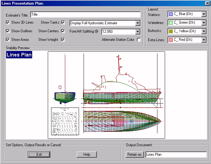
This 'Lines Presentation Plan' dialog box is the following:
The ‘Show 3D Lines’ checkbox allows displaying or hiding the virtual ship’s complementary lines (silhouette, sheer, openings, …).
The ‘Show Outlines’ checkbox allows displaying or hiding solid’s face outlines.
The ‘Show Areas’ checkbox allows displaying or hiding ship’s SAC.
The ‘Show Tanks’ checkbox allows displaying or hiding ship’s tanks.
The ‘Show Centers’ checkbox allows displaying or hiding ship’s centers (center of buoyancy, center of gravity, …).
The ‘Show Weight’ checkbox allows displaying or hiding ship’s weight curve.
The ‘Estimate Title’ input field allows specifying hydrostatic estimate ‘s optional title.
The ‘Hydrostatic Estimate’ selector allows selecting which kind of hydrostatic estimate must be inserted in the lines plan (default is ‘Display Short Hydrostatic Estimate’, but ‘No Hydrostatic Estimate’ is also possible, as well as ‘Display Full Hydrostatic Estimate’ for a complete estimate).
The ‘Fore / Aft Splitting @’ input field allows locating the transverse plane according to which the body plan stations are considered as fore stations (displayed on the right) or after stations (displayed on the left).
The ‘Alternate Stations Color’ checkbox allows alternating station’s color in order to make their identification easier, especially around the midship area.
The ‘Layout’ frame contains the following color selectors:
- The ‘Stations’ selector allows selecting the stations color (except if the ‘Alternate Stations Color’ is checked).
- The ‘Waterlines’ selector allows selecting the waterlines color.
- The ‘Buttocks’ selector allows selecting the buttocks color.
- The ‘Extra Lines’ selector allows selecting the complementary lines (silhouette, sheer, openings, …).
The ‘Output Document’ frame allows retaining the current lines presentation plan among the 2D reports by clicking on the [Retain] button (the associated input field allows naming the retained report).
At last, the following buttons are also available:
The [Exit] button can be clicked for exiting the ‘Lines Presentation Plan’ dialog box (the current lines plan will then be lost if it has not been previously printed , exported or retained among the 2D data).
The [Help] button allows displaying the online help (Internet access necessary).
Outputs :
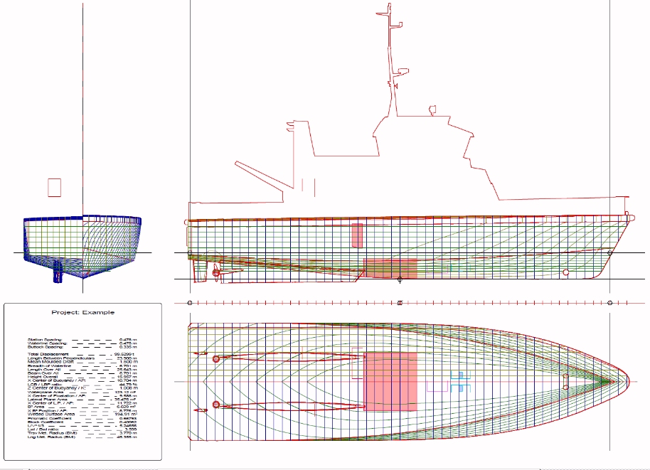
After clicking on the [Retain] button, the current lines plan is retained among the 2D reports, with its current layout options:
Limitations:
The only limitation concerns the lines plan sectioning grids.
Typical Use:
Calculating ship’s Lines Presentation Plan.
Example:
Open the ‘Example Ship.m2a’ file and double click on ‘Intact 100% Supply’ in the 3D browser to select this virtual ship:
Select '/Tools/Presentation Plan' in the menu bar.
Click on the [OK] button directly to validate the default Lines Plan Grid settings and start the lines plan calculation.
The Lines Presentation Plan dialog box then pops up, allowing to set lines plan layout options (see below).
Try various display options and click on the [Retain] button to retain the lines presentation plan among the 2D data.
Click on the [Exit] button and on the [2D] tab to display the retained plan.


