Go to Help Summary Go to FAQ Summary
Menu bar/Tools/Sounding Tables
____________________________________________________________________________________________________________________
Purpose:
Automatically calculates current tank's sounding tables (i.e. tank capacity table according to sounding / ullages in a given trim range) as soon the tanks can be sounded.
It is recalled that tanks can only be sounded when they contain a sounding pipe (i.e. an affiliated line in the ‘Sounding Pipe Layer’ declared on [Ship] tab's [Hydro] page). See FAQ for more details.
Inputs:
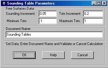
The following dialog box pops up when the function is selected:
The ‘Sounding Increment’ input field allows entering the free surface increment (heel = 0°).
The ‘Trim Increment’ input field allows entering the trim increment in current length unit. As 11 (0 to 10) trims are automatically calculated for each sounding, this increment must be correlated to trim range's limits
The ‘Minimum Trim’ input field allows entering the trim range's minimum value. According to the current Trim Increment value, the ‘Maximum Trim’ value is automatically updated accordingly (maximum trim = minimum trim + 10* trim increment).
The ‘Maximum Trim’ input field allows entering the trim range's maximum value. According to the current Trim Increment value, the ‘Minimum Trim’ value is automatically updated accordingly (minimum trim = maximum trim - 10* trim increment).
The input field located in the ‘Document Name’ frame allows naming the 2D folder in which the reports will be created.
Finally, when the input data are set:
The [OK] button can be clicked for starting the tank calibration.
The [Help] button allows displaying the online help (Internet access necessary).
The [Cancel] button allows cancelling the calculation.
Outputs:
After clicking on the [OK] button, a 2D folder is created, containing the sounding tables corresponding to the entered data and displayed in the [2D] tab.
The following reports are automatically created for each soundable tank:
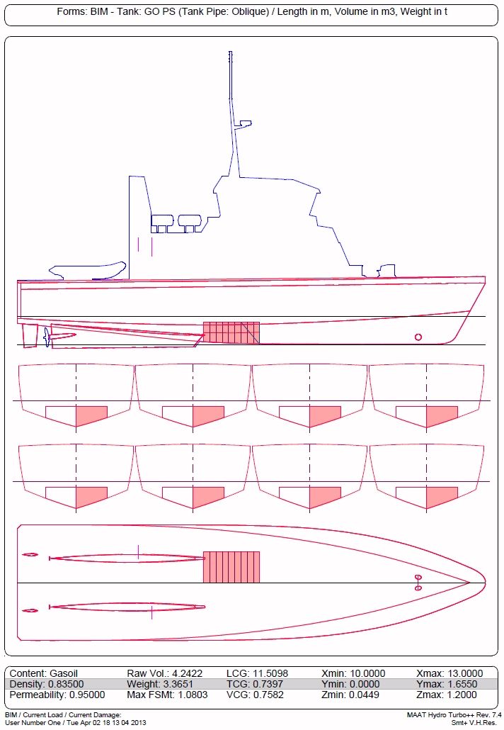
1: Tank Location / Presentation Plan:

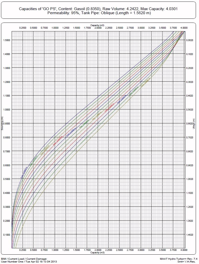
2: Sounding Curves:
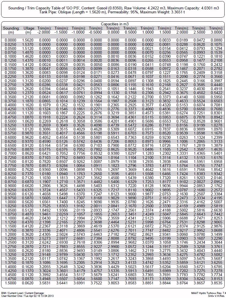
3: SoundingTable:
Limitations:
- For obvious reasons, the sounding curves and tables can only be calculated for the soundable tanks, i.e. tanks containing a tank pipe (See FAQ for more details).
Typical use:
Calculating ship tank's sounding tables for onboard use (use ‘/Tools/Tank Calibration’ for getting ship tank’s design data).
Example:
Open the ‘Example Ship.m2a’ file and double click on ‘Damage 100% Supply’ in the 3D browser to select this virtual ship:
- Select "/Curve/Line/Line" in the menu bar.
- Type '12.9,0.1,0.1[Return]' to input tank pipe's bottom.
- Type '12.9,0.1,1.2[Return]' to input tank pipe's top.
- Check the 'Tank Pipe Layer' on [Ship] tab's [ Hydro] page.
- Click on the [Data] tab to display the corresponding page.
- Rename the created line 'GO PS Tank Pipe' in the 3D browser
- Set 'GO PS Tank Pipe' line's layer to the current 'Tank Pipe Layer'.
- Drag the 'GO PS Tank Pipe' line with the 3D browser to drop it in the 'GO PS' tank.
- Select '/Tools/Sounding Tables' and validate directly.


