Go to Help Summary Go to FAQ Summary
Menu Bar/Tools/Lines Presentation Plan
Menu Bar/Tools/Lines Presentation Booklet
____________________________________________________________________________________________________________________
Purpose:
This function is intended to allow defining ship’s sectionning grids in order to provide the lines needed by the 'Lines Presentation Plan' and 'Lines Presentation Booklet' functions. When the grid data are validated, the lines plan is calculated and a 'Lines Presentation Plan' / 'Lines Presentation Booklet' dialog box is displayed, allowing to set various layout options in real-time before printing, exporting and/or retaining it among project’s 2D data (see ‘Lines Presentation Plan’, see ‘Lines Presentation Booklet’).
Inputs:
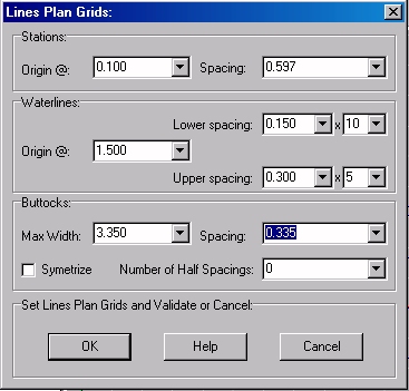
This Dialog Box allows entering lines plan’s sectioning grids:
The ‘Stations’ frame allows defining the stations grid:
- The ‘Origin @’ input field allows fixing stations grid origin, understood that station’s spacing is constant (see ‘Spacing’ below) and that the grid automatically covers ship’s longitudinal extent. The associated selector allows pre-setting this origin from a set of predefined values (x=0, x= AP, x=MP, x=FP), as well as typing any specific value.
- The ‘Spacing’ input field allows fixing stations grid’s constant spacing, understood that the number of stations is automatically set to cover ship’s longitudinal extent. The associated selector allows pre-setting this spacing from a set of predefined values (LBP/10, LBP/20, LBP/40, LBP/50, LBP/80, LBP/100), as well as typing any specific value.
The ‘Waterlines’ frame allows defining the waterlines grids:
- The ‘Origin @’ input field allows fixing waterline grid’s vertical origin, understood that different spacings can be specified independently below and above this origin (see below). The associated selector allows pre-setting directly this origin to the current Dwl height if necessary.
- The ‘Lower Spacing’ input field allows fixing waterlines constant spacing below the vertical origin, understood that the number of these lower waterlines can be specified in the ‘x’ input field located beside. The associated selector allows pre-setting this spacing from a set of predefined values (Draft/5, Draft /10, Draft /20), as well as typing any specific value.
- The ‘x’ input field allows specifying the number of immersed waterlines. The associated selector allows pre-setting this number from a set of predefined values (0, 5, 10, to reach K point, to reach ship’s lowest point), as well as typing any specific value.
- The ‘Upper Spacing’ input field allows fixing waterlines constant spacing above the vertical origin, understood that the number of these topside waterlines can be specified in the ‘x’ input field located beside. The associated selector allows pre-setting this spacing from a set of predefined values (Draft/5, Draft /10, Draft /20), as well as typing any specific value.
- The ‘x’ input field allows specifying the number of topside waterlines. The associated selector allows pre-setting this number from a set of predefined values (0, 5, 10, to reach ship’s highest point), as well as typing any specific value.
The ‘Buttocks’ frame allows defining the buttocks grid:
- The ‘Max Width’ input field allows locating the buttocks grid limit and the associated selector allows pre-setting this width automatically to current model’s Bmax if necessary, as well as typing any specific value.
- The ‘Spacing’ input field allows fixing buttock grid’s constant spacing, understood that the number of buttocks is automatically set to reach the specified ‘Max Width’ (see above) and that a certain number of additional ‘half-spacing’ buttocks can be added beside the Centreline (see below). The associated selector allows pre-setting this spacing from a set of predefined values (Bmax/5, Bmax/10, Bmax/20), as well as typing any specific value.
- The ‘Number of Half-Spacing’ input field allows specifying the number of addition ‘half-spacing’ buttocks to insert in the grid beside the centreline. By default, no half spacing buttock is added, but the associated selector allows pre-setting this number from a set of predefined values (0, 1, 2, 3, 4, 5, 6, 7, 8, 9, 10), as well as typing any specific value.
- By default, the buttocks are created on portside (Y>0) but, if necessary, although generally useless, the ‘Symmetrize’ check box allows setting the buttocks symmetrically on both sides.
At last, when all the sectioning grids are defined:
The [OK] button can be clicked for calculating ship’s lines plan and displaying it in the Lines Plan Results dialog box (see below).
The [Help] button allows displaying the online help (Internet access necessary).
The [Cancel] button allows cancelling the functtion.
Outputs :
After clicking on the [OK] button, the lines plan calculation starts according to the entered data and the 'Lines Presentation Plan' / 'Lines Presentation Booklet' dialog box, detailed below, finally pops up, allowing to control lines plan’s layout accurately.
Limitations:
The sectioning grid parameters must be set with care and the spacings must be large enough to avoid calculating too many lines.
For obvious reasons, zero spacings are refused.
Typical Use:
Calculating ship’s Lines Presentation Plan / Booklet.
Example:
Open the ‘Example Ship.m2a’ file and double click on ‘Intact 100% Supply’ in the 3D browser to select this virtual ship:
- Select '/Tools/Presentation Plan' in the menu bar.
- Click on the [OK] button directly to validate the default settings and start the lines plan calculation.
- The 'Lines Presentation Plan' / 'Lines Presentation Booklet' dialog box, then pops up, allowing to set lines plan layout options.

